Scratch building a Non Corridor 3rd Diag. C83
History
The photograph below (by R J Doran) which appeared in Great Western Railway Journal No.50 was the inspiration for building the model. Trawling through my various books on GW coaches, I deduced that these two were a Third Non Corridor Diag.C83 and a Brake Third Non Corridor Diag.D132. As I was unable to locate any kits for these two carriages, I decided that I would have to scratch build them myself.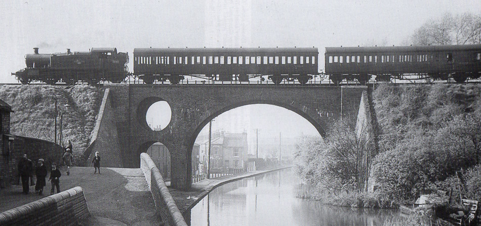
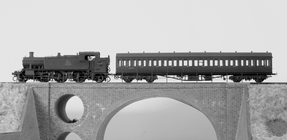
One down, one to go!
Prior to commencing any construction, detailed General Arrangement drawings were prepared in Autocad using photographs and overall dimensions gleaned from J.H. Russell's Great Western Coaches Appendix Vol.1 and Michael Harris's Great Western Coaches. These were then used to prepare construction drawings including details of the various layers.
Bodywork
I had recently been reading Geoff Kent's excellent articles on scratch building carriages in styrene sheet (MRJ Nos. 222, 226 & 228) and adopted some of his techniques with a few of my own adaptations. I like to glaze my carriages after painting, so I made up the sides with three laminations, the outer 0.25mm thick the other two 0.50mm thick. The middle layer holds the glazing which is retained by the other two layers. The glazing is slid in from above after painting. As the drop lights are set back from the outer face a fourth layer was needed to retain the glazing to those. These only needed to be the width of the doors. Each layer was drawn by hand onto styrene sheet taped to a parallel motion drawing board to keep everything square. The styrene sheet was then transferred to a cutting mat where the various layers were cut out using the old fashioned method of scalpel and steel rule. The rounded corners of window openings were formed with a small needle file. If I was going to do a lot of coach building in styrene, I think I might invest in a sillouette cutter!
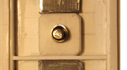
These carriages had very little tumblehome which made life a lot easier. Once the middle and inner layers had been bonded together, the tumblehome was formed on the outer face by scraping, filing and sanding. The outer layers were then cut out. At this point, all the holes for door handles, grab handles and bump stocks were drilled out, the doors scribed and the postions of hinges marked, following which the outer layers were bonded to the others. It was very important to make sure that all three layers were accurately aligned. To achieve this, they were lightly tacked in place with solvent and, when happy with the result, solvent was fed in around the edges, allowing capilliary action to do the rest. At this point, the door stops, hinges and end grab handles were fitted. The door stops and grab handles are 0.44mm brass wire, the hinges are styrene micro rod.
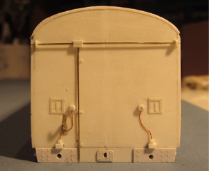 The ends were tackled next. one end needs a lot more detailing than the other. I was going to make the electrcal leads capable of being connected between the two coaches but everything was just a bit too small. The holes for buffers and couplings were also drilled out at this stage. Next up I cut out the floor, a single layer 1mm thick sized to fit between the sides and the ends. The base of the roof has three layers, 0.75mm bottom to fit inside the body panels, 0.50mm middle that fits inside the ends but projects over the sides to form the gutter and 0.75mm top that fits inside the ends but is profiled to fit inside the long edges of the roof (see later). Although the middle layer fits inside the ends, its overall length is longer as the gutters project beyond the ends. These projections are very fragile and are esily broken.The three elements were fixed toether with solvent.
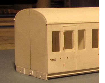
One end was now fixed to one of the sides, checking that everything was level and square. the other end and side were then fixed to each other. After the initial set had taken place but before hardenning, the two elements were brought together and fixed with solvent. The floor was slipped loosely into place to check that everything was square. The inner door panels had been cut 1mm short at the bottom providing a stop for the floor to ensure that it was flush with the bottom of the sides. Similarly, the roof base could be dropped into place to prevent the sides from bowing at the top.
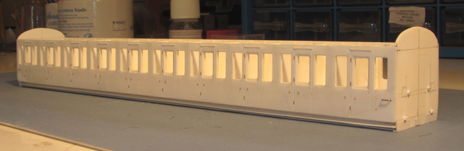
Please note that the above photo was taken after the solebars and steps had been fitted! To provide some stability, I first fixed a 1 x 2.5mm backing strip to the underside of the floor, which was then faced with a .5mm thick strip to represent the web of the channel section solebar. The flanges were made up 0.25mm thick, the lower one extending to the rear of the solebar. 0.25mm thick brackets (vertical legs only!) were fitted at appropriate positions along the solebar. These also acted as stops against which to set the 0.5mm thick running board to help keep it straight and level. A couple of days later, when measuring up for the underframe bracing, I discovered that the gap between the solebars was 2mm less than it should have been. It transpired that I had fixed both backing strips the wrong side the lines that I had marked out on the underside of the floor! Fortunately I was able to remove both solebar/running board assemblies intact with a sharp scalpel and refit them in their correct locations.
 Somewhere around this point, I fitted the 1mm thick partitions. These are sized to come up to the underside of the roof base. I used Geoff Kent's method for constructing the roof (see ref to MRJ above) which basically involves fixing two thin skins of plasticard over shaped formers. The end formers are positioned to sit just inside the coach ends. I preshaped the skins by taping them to a balsa wood former and applying boiling water.Fixing the skins can be quite tricky. I first tacked a short length of one edge in place against the top element of the roof base (see above) then, after checking that everything was correctly aligned, ran solvent along the rest of that edge. Once it had gone off, I repeated the exercise for the other side. The tricky bit was keeping the skin tensioned along its complete length so that it sat tight against the formers. It is of course essential that the skin is cut to exactly the correct width! I also ran solvent along the joint between the skin and the end formers. Once the first skin has gone off, the second can be applied in the same manner. The skins were cut slightly over length and subsequently filed flush with the coach ends. The positions for the roof ventilators were marked out and drilled. Remember that these are offset from the centreline of the coach! The ventilators came out of my stock box, I am pretty sure they originally came from MJT.The roof was not fixed at this stage.
Before proceeding any further, I decided it might be wise to check the ride height of coach. I therefore removed a pair of Bill Bedford bogies from one of my Mk 1's and packed the out from the floor of the coach until the holes for the buffers were at the correct height. This turned out to be 2.75mm, pretty much what I expected . I therefore laminated a pair of bolsters 12 x 12 x 2.75mm thick. These were then drilled 4.75mm for the brass tube that would act as the pivot for the bogie.
 Holes were marked out on the coach floor and drilled for the 6BA bolts that would retain the bogies. The bolts were then secured in place with epoxy adhesive. 4.75mm lengths of the brass tube were secured into the bolsters (leaving 2mm showing) and the whole centred over the bolts and secured with solvent. The bogies were reattached and the ride height checked again. Happily everything was fine, so the bogies went back on the Mk1 and I could move onto the underfloor detailing.