Canal Basin and Lock
Canal
The canal section of the layout is based on the Worcester and Birmingham Canal where it passes under the railway to the west of Rainbow Hill Junction in Worcester. This was one of the first bits of the layout to be built as it needed to be fairly complete before the bridge carrying the main line. The base of the canal is 6mm ply and to achieve the necessary depth the 15mm MDF decking to the remainder of the layout was packed up on strips of 6mm ply. The brick walls are from Slaters range, painted with Humbrol enamels. On the model, the entrance to the wharf that passes under the road under the road on the left has been bricked up. In real life this wharf has now been converted into a marina and the access is still open. However, on the model, the wharf area has been filled and is now occupied by the loco shed. I had originally intended to have waterfront industrial premises to the right of the basin to form a scenic break at that end of the layout. However, this will now be modelled more along the lines of the prototype with the open wharf area overgrown with substantial trees growing at the foot of the embankment that will provide the scenic break.
Canal Lock
The logic
When I built the canal at the start of the project, there was no intention to have a lock as there was none on the prototype. However I had for a long time pondered the problem of how to deal with the canal disappearing into the backscene as it would look wrong when viewed from any angle other than the one in which it was represented on the backscene. Eventually, many years later, an answer came to me. To put in a rising lock with the bottom gates tight up against the back scene. Assuming this was a single lock, the canal beyond would then not be visible from a ground level view point. Fortunately, there was just room to fit this arrangement between the railway bridge and the backscene.
The model
Detailed drawings were prepared in Autocad, the information being derived from the many photographs of locks on the Worseter and Birmingham canal that I found on the web. There was no way that I was going to be able to dig up the canal, so I decided to build the walls and gate as a drop in element that would sit on top of the existing 'water'. The edgings to the canal in the area to be narrowed would, however, need to be broken out along with the bollards between the road and the towpath. Before doing this, but not until after a minor accident, I decided it might be a good idea to temporarily remove the signal on the embankment just to the right of the bridge as this was very vulnerable!
The photo on the left shows base for the lock structure, cut out of 1.5mm styrene sheet, with one wall attached. The cut out on the left hand side is for the overflow outfall. The walls sit on top of the base but the facing brickwork is carried down to water level as are the gates, the cut out for which is at the top of the photo. The new ground levels will be built up once the lock structure is complete and painted. The basic wall structure comprises two 1mm skins of styrene separated by spacers (see below). To help with the curvature, the inside face of the styrene was heavily grooved and reinforced with an extra layer. The walls wewre finall faced with Slater's english bond brickwork. This was cut to extend 1.5mm below the basic wall structure to mask the edge of the base. The arch to the overflow outfall was scribed onto styrene sheet. The brick and stone copings are laminated from styrene sheet, the top layer having been scribed while still on the sheet (makes it much easier to keep things parallel). The set back at the end of the wall is the start of the recess to take the gate when open.

Only one wall was permanently fixed initially as it would be rather difficult to paint the brickwork with both walls in place. However I secured it in place on a temporary basis, firstly to take progress photographs and secondly to double check the fit of the gates. I'm not exactly sure of what purpose the platform on the right hand side served, not all the locks appeared to have it. Curving the styrene for the small radius on this wall was made easier by taping the sheet to a former and plunging into boiling water.
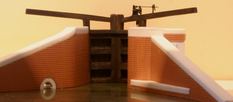
The gates were maded from basswood. The nearest size I had available was 4 x 4mm. This was trimmed down to 3.3 x 4.0 for the hinge posts, 4.0 x 3.3 for the top/push rail and 3.3 x 3.3 for the closing posts and cross rails. A strip of 0.5mm plywood was cut the height of the gates. This was scribed to represent the planking and marked out with the positions of the posts. The posts for one gate were cut to length and glued in place with PVA, followed by the top and intermediate rails. Once set hard, the ply backing was trimmed to size. This was then repeated for the other gate. The gate posts were chamferred to a third of their width where they meet. This would have kept them reasonably water tight on the real thing. They were then ckecked for fit and glued together with PVA while in position. As the rear of the gates will not be seen, this joint was subsequently reinforced with a fillet of epoxy. The gates were painted with Railmatch weathered black, diluted with white spirit to let the grain of the timber show through.


It took me quite sum time to sort out the paddle gear. When I first drew up the gear, I found plenty of photographs taken from the rear of the gates but no close ups taken from the front and had to make a lot of assumptions. However, there were areas that didn't seem quite right and bits that seemed to serve no purpose. Eventually I found the shot I was looking for, everything finally made sense and I was able to modify the drawings. What would I do without Autocad! The gear was fabricated from a combination of styrene sheet (10, 20, 30 and 40 thou) and brass rod (0.3, 0.5 and 0.7mm diam.). I refrained from cutting teeth on the gear wheels, 0.3mm pitch is very small and, after all, the lock gates are at the very back of the layout! The main element was first secured to the gates with epoxy and the rest built up in-situ, the support brackets being fixed with superglue. The gear was then given a coat of Railmatch weathered black.
Back to the walls. These were painted dark blue (Humbrol enamel 77 matt) to represent engineering brickwork before being given a wash of acrylic 'mortar'. I made up a fairly wet mix of white/black/yellow ochre which was applied to the walls and immediately wiped off leaving mortar in the joints. I bought a Reeves starter set of 12 x 10ml acrylic artist colours for under ten euros, which is a great value if you don't use a lot of paint. This toned down the blue a little more than I wanted so a tiny amount of blue paint was dry brushed over the face of the brickwork. Subtle staining of the walls was applied using white acrylic and weathering powders (mostly green and light grey) were used to further tone down and stain the brickwork.
I had drawn up contours and a grid on the Autocad plan and used these to produce profiles to create the 'eggcrate' construction for the landform either side of the lock. This also included the towpath and the extension of the public road beyond the bridge. The profiles were cut from offcuts of mounting board and slotted together to form a rigid structure. This was then covered with two layers of strips of thin card secured with PVA. The thin strips allow the card to follow the profiles without creasing. The road and paths were cut out of thicker card. A final thin layer of papier mache took out any sharp edges from the eggcrate structure.
The towpath and flat areas adjacent to the lock gates were surfaced with a mix of ash and coal dust (left over from surfacing the loco shed yard) and the road kerbs were painted with acrylics. The road and adjacent footpath were given a coat of grey enamel onto which talcum powder was sprinkled to achieve a textured surface. Prior to embarking on the detailing of grass, weeds, brambles, etc, the rest of the area was given a basic ground cover of a mix of dyed sawdust and various scatter materials.


You will notice that the stone edgings to the canal have been removed. in due course these will be replaced with blue brick edgings to match those on the lock walls and replicate those found on the prototype. Needless to say, the 'water' did not go unscathed during the chiselling out of the plasticard edgings and will need resurfacing. New brick edgings are now in place and the water has received a fresh coat of paint and several coats of varnish. The footpath has been surfaced, the banks have now grown a lot of vegetation and a temporary backscene has appeared.

The canal wouldn't look right without a barge and I decided that at that time, with the canal in a sorry state, the barge would probably have rotted out and settled to the bottom. It was built out of styrene, the base is 0.5mm thick and the sides 0.25mm thick. I had to do a few drawings to get the profiles of the sunken sides correct. The first picture shows one side in place, the second shows the barge complete and in primer an finally the barge in place along side the wharf. The water in the bottom of the barge was painted with the same mix that I used for the water in the canal


