MORE LOCOMOTIVES
70018 Flying Dutchman (Contd)
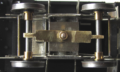
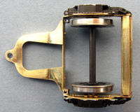
Front Bogie
The bogie uses the Comet etches as a basis. However, it is pivoted rather than being on a swinging arm. I have also attempted to spring it in a similar way to the prototype.
As I prefer the axles to run in bearings, the slots in the chassis were opened out accordingly using needle files. The axles are sprung with guitar wire. Later on, these need tweaking to until there is just enough downward pressure not to lift the front drivers off the rails. 2x1mm brass tubes form lateral rails that bear on the mounting plate on the underside of the chassis. Side rails are cosmetic only and slightly lower than the bearing rails. The guard irons on the etched sides are too short, so they were cut off and longer ones were fabricated and soldered inside the frames. These are not shown here.
A plate cut from 0.45mm thick n/s was soldered to the underside of the bogie. This was slotted to take the pillar mounted on the chassis. The brass retaining strip is tightened against the pillar, retaining both wheelsets and bogie while still allowing the bogie to slide laterally. I did experiment with lateral springing, but eventually dispensed with it. All the modifications to the bogie were worked out in Autocad to ensure that it carried the loco at the correct height.
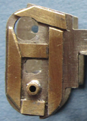
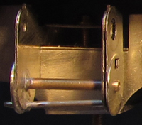
Rear Pony Truck
As mentioned previously, Mike Garside has produced an excellent etch for the Brit pony truck and kindly hand delivered one to me at Trainwest.
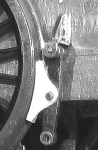
I added a few tweaks of my own: the corners were reinforced with short lengths of square brass tube (this makes the whole thing a lot more rigid) and a length of rectangular brass tube was soldered on the top of the rear cross member, I sprung the wheels as per Mike's design but I also used two lengths of spring wire mounted on the chassis and bearing down on the bearing pad (see below) to exert a little downward pressure.
The brass tube on the cross member acts as a bearing pad and sits up against two posts soldered to the chassis which is more or less a reverse of what happens on the prototype! The posts were cut slightly over size, soldered in place and then filed to the correct height. This was done slowly, checking regularly with the rolling chassis (with truck fitted) on the track until there was a good electrical connection between both rear drivers and the track.
The axle boxes/springs were rescued from the Hornby donor. I did have to spend a couple of hours filing about a millimetre off the rear faces but that was a lot quicker than starting from scratch. The Comet ones would have required the same treatment and are not as accurate. The rear of the axle boxes were drilled out to accommodate the sprung pin point bearings.
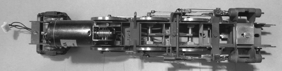
Wheels, gearbox and motor
As they have already featured in the bogie and truck, now would seem a good pint at which to talk about wheels. All wheels are all from Alan Gibson, the drivers were assembled on their axles with a GW wheel press once the Ultrascale crank pins had been fitted and trimmed to length. Slots were machined in the ends of the driving axles (by my good friend Morgan Gilbert) to enable the wheels to be pinned. Needless to say, hornblocks, gearbox and any washers that may be required need to be slid onto the axles first! Morgan also drilled the ends of the axles as per the prototype.
The gearbox is a High Level Road Runner+. This was chosen in preference to a High Flier as it has mountings for a 16mm can motor, in this case a Mashima 1626. The swinging section of the gearbox was spot soldered in place once I was happy that everything was running smoothly. This combination allowed me to take advantage of the large firebox area behind the driving wheels on the Pacific to hide the motor to the rear of the gearbox driving the rear axle and to fit the false bottom to the boiler below footplate level.
Cylinders, Motion and Valve Gear
I really wanted to use as much of the Comet valve gear as possible, so I plotted everything carefully in Autocad before starting on any fabrication. With the changes that I had already made to the chassis, everything looked OK although the combination levers did appear as though they may be a little short.
I started with the cylinder assembly first. Once the basic structure had been folded up, it became apparent that it was too narrow front to back and I ended up packing out the rear face with scrap etch before fitting the overlay. To provide more support for the piston rod, the holes in the etch were opened up and lengths of brass tube soldered in place. With the basic structure complete, I fabricated a n/s plate that was subsequently soldered to the underside of the cross members between the cylinders. This strengthened the structure, raised the cylinders to the correct height and, with the valve gear temporaily in place, fixed its location in the oversize slot in the side frames.
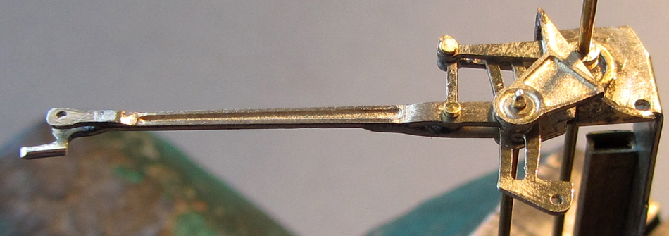
Before finishing off the cylinders, I made a start on the valve gear to make sure everything fitted. Wherever possible, and wherever they occured on the prototype, I have used forked connections. I feel this removes the sloppiness sometimes encountered. These joints are made up with brass lace makers pins (for method see section on coupling rods) with the heads filed to an appropriate size and thickness.
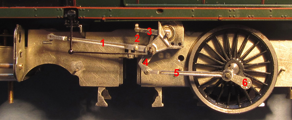
The nomenclature for the various bits of valve gear is that used by Comet in their instructions
1. Valve rod
2. Lifting arm link
3. Lifting arm
4. Expansion link
5. Eccentric rod
6. Return crank
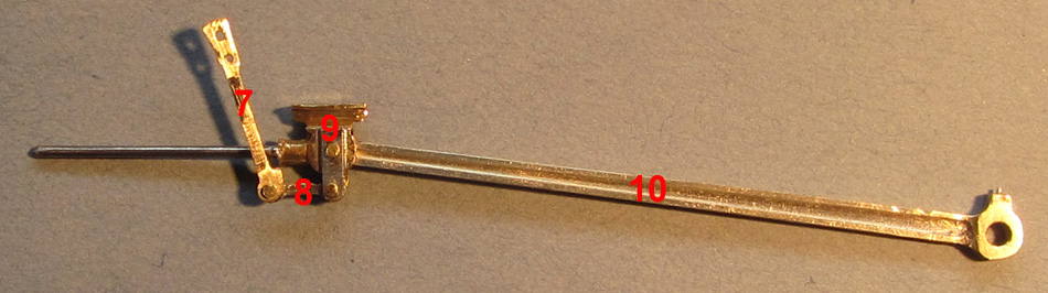
7. Combination lever
8. Union link
9. Crosshead
10. Connecting Rod
I fabricated the motion/valve gear in three sub assemblies:
Crosshead + connecting rod + combination lever + union link
I removed the cast brass piston rod then drilled the cross head for a steel rod, which was then soldered in place. The casting was cleaned up with needle files until it would run smoothly in the slide bars. I soldered a strip of n/s to the face of the cross head to make it look a little more like the prototype and this also provided a more stable connection for the union link. The connecting rod was made up as per the instructions, but scrap etch was used to thicken the boss.
Valve rod + lifting arms + lifting arm link
As the valve rod would not be moving, it was cut to length to fit against the face of the rear valve chest. To help stabilise the valve rod/combination lever a bracket was made up and soldered to the valve spindle cross head guide (see details below) to act as a pivot for the pinned joint between these two parts. Forked joints were added to both ends of valve rod. The separate lifting arm link from the kit was used and the one forming part of the valve rod etch was removed. The forked joint at the outer end of the valve rod covers the pinned joints for both lifting arm and expansion links. I did not use the valve rod fork provided in the kit for this. I added a n/s spacer between the pair of lifting arms for the joint to the motion bracket. Once soldered between the arms, it was filed to shape and drilled for the pin. This makes subsequent assembly easier.
Expansion link + eccentric rod + return crank
I added a forked joint to forward end of the eccentric rod and added a n/s boss to the rear face of the other end to replicate the prototype. The return crank was soldered to an Ultrascale brass crankpin nut (remember to push out the half etched bolt heads first) then tapped with a steel crankpin. The crankpin nut was then filed down to about half its original thickness.
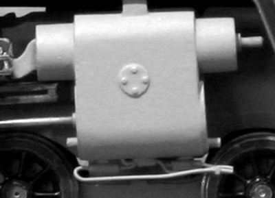
I have used the lubricators from the host loco as these are nicely detailed and are reasonably good fit. The locating pips certainly need removing from the bottom of the lubricator pips so as to sit on the Comet brackets. The pips on the top are designed to sit in holes in the footplate. These can be removed and the holes in the footplate filled in. This not only looks better but makes the lubricators less susceptible to damage when separating body and chassis.
Brakes
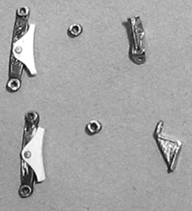
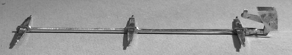
Unfortunately the combined brake hangers and shoes provided with the kit weren’t quite correct. However, by filing off the shoes, I was able to use the hangers as they were the right overall length. They needed drilling to take a pin to locate the shoes in the correct position. Once the first one was done, it was used as a template to drill the others. Short lengths of brass rod were soldered into the hangers to mount the shoes The hangers also needed attacking with needle files to get them to the correct shape. The shoes were built up on the hangers in three pieces (front, back and filler) from white styrene. The beauty of this system is that they won’t short out if they come into contact with the wheels. Mounting brackets were made up from nickel silver strip and spacers from small bore brass tube. The spacers and shoes were threaded onto the pivot wires on the chassis, followed by the brackets which were secured to the side frames with epoxy, although I guess I could have used a lower melt solder..
The only item of operating gear in the kit was a central pull rod designed to be used with brass wire cross shafts. I made up some prototypical cross shafts from n/s strip, suitably shaped and with short lengths of 0.5mm n/s rod soldered onto the ends to take the bottom of the brake hangers. The pull rod was drilled out to take these and the assembly soldered up once I was happy that everything was square. Although it’s largely hidden, I did model part of the operating gear and supporting bracket. The whole assembly ‘floats’ when threaded onto the brake hangers, allowing easy removal.
CylindersWith everything tested, I decided it was time to finish off the cylinders. The Comet white metal castings needed quite a lot of work with scalpel and files to get a good fit. The fixings on the cover plates are a little over scale and maybe I should have filed them off but hey are not so prominent once painted and weathered. The pipework on the bottom of the cylinders was fabricated from soft copper wire and small bore brass tube.
Sanding gear
Sand pipes on the Standards can be pretty fiddly. I started by drawing them on the computer to make sure they didn’t clash with brakes, springs or electrical pick-ups, then transferred the information onto a piece of mounting board. The small brackets, which were fabricated from n/s strip (twisted, bent, filed to shape and drilled for the pipes), were stuck to the board with super glue and soft copper wire was bent to the correct shape, threaded through the brackets and soldered in place. I then tinned the thin PCB strips, place them face down on the wires and, with plenty of flux, soldered them in place. I was able to use this method as on the model the rear face of the pcb and the rear face of the brackets are in the same plane. Once complete, they were removed from the board with a scalpel and any trace of superglue removed before being primed prior to fixing. The brackets are notched to hook over the bottom of the spring hangers so it just required the pcb strips to be fixed to the rear of the main frames with epoxy. There are two sand boxes on the Brits but the front one is hidden so I am afraid I only modelled the one at the rear. This was made from styrene and secured between the frames with epoxy. There was only a very small point of contact between the two so I added a hidden leg that bears on the frame spacer below. The feed pipes are 1.5 x 1.5mm styrene.
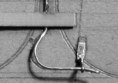
ElectricsI used sprung wire electrical pick-ups soldered to pcb pads fixed to the captive nuts on the frame spacers with 12BA bolts. The two halves of the pads were electrically separated and plastic washers were used to stop the bolts from shorting out. Care also had to be taken to ensure that these pads did not make contact with the sand pipes. Power is only picked up from two sets of driving wheels as there was too much in the way on the rear set. However, as power is being picked up from all the tender wheels, I do not think this is a problem. I have some Hornby plugs and sockets but, as my plugs didn’t seem to fit the socket on the tender, I re-used the wiring from the Hornby chassis. See Fig 30. This is a bit messy at the moment but will be tidied up in due course.
TenderApart from the alterations to the body already mentioned, I have done very little with the tender except to drop in some Ultrascale P4 wheel sets and bend the electrical pick-ups to suit them.
Painting and weathering
I have to admit that this is the bit that I enjoy the least. I am not great with an airbrush but I persevere and usually end up with something acceptable. At least I hope I do.
The chassis was broken down to its various components, scrubbed, dried and primed with Halfords grey primer. I have found that, in recent years, their aerosols throw out the paint a lot more thickly than they used to, so it’s a matter of giving each item a couple of quick passes with the can, checking for coverage between each pass. I try to hit awkward corners first and then fill in between. As most of the chassis components were made with an interference fit, adjoining faces were masked with tape, as were hornblock guides, slide bars, crossheads, con rods, captive bolts, etc. Once dry any other abutting edges had the primer removed. The cylinder casings needed a bit more filler and were then re-dusted with primer. I used matt Humbrol enamels for the airbrushed top coats, a mix of 33(black), 112(tarmac) and 62(leather). Incidentally, I always remove the masking after priming and re-mask for the top coats.
The same mix was used to brush paint the firebox, ashpan and other bits below the footplate on the body. The ashpan had a little more 62 added. These areas and the chassis also received some attention with weathering powders.
The wheels were thoroughly degreased before the rims were darkened with gun blue. The wheelsets were then slotted into a mounting board ‘chassis’ that held them firmly in place while they were airbrushed with the same mix as the chassis. Once dry, any paint was removed from the treads and the wheels were polished with a soft cloth to give them a light sheen.
I had debated hard and long with myself as to how heavily the loco should be weathered. Photographs show that 70018 was actually pretty grubby before she went into Swindon for a major overhaul in 1959. Not as bad as some of the Brits were allowed to get in later years but not as beautifully maintained as she was maintained when hauling trains like the Capitals United. In the end I decided on fairly dirty but with a slight sheen to show that someone cared and had made an effort to make her look a little more respectable. I have a Bachmann Hall awaiting ‘treatment’ that is going to be seriously grubby, so I decided to have a practice run on that as any mistakes could be covered up later. The whole body was given a light coat of a mix of 112(tarmac) and 62(leather). When I was happy with that, the top of the boiler and firebox, footplate, cab front and roof were given another coat, this time with some 33(black) added. The tender was airbrushed at the same time as the body. I left everything to harden off for a couple of days before polishing the boiler, firebox and cab with soft cloths, cotton buds and bristle brushes to achieve the finish I wanted. The smokebox door and smoke deflectors received the same treatment. A small amount of detailed weathering was carried out with powders.
Now all that remains to be done is to add some coal in the tender and some suitable crew in the cab.